

Chiller and AHU Fault Detection: Data to Diagnosis
- Publised October, 2026
-
Duc Nguyen (Dwight)
Fault, Alarm & Maintenance: Detect chiller and AHU faults from BMS data with tested rules and delta T checks.
Table of Contents
Toggle
Key Takeaways
A fault signal is not a confirmed failure. Low chilled-water delta T, supply-air temperature deviation, or excess compressor energy must be interpreted against load, operating mode, and equipment design.
Chiller FDD and AHU diagnostics are interdependent. A distribution-side problem can degrade plant performance, while a plant-level problem can create alarms across several AHUs.
Rules should be validated before AI is introduced. Physics-based checks, sensor validation, operating-state conditions, and time persistence establish a reliable diagnostic foundation.
Detection must lead to maintenance decisions. Useful FDD outputs identify supporting evidence, competing causes, required inspection steps, and post-repair verification criteria.
A chiller can maintain its chilled-water supply temperature while consuming more electricity than expected. An air handling unit (AHU) can maintain its supply-air setpoint while a leaking valve wastes heating and cooling energy. Neither condition necessarily triggers a conventional BMS alarm.
This creates a difficult problem for facility operators: equipment may appear healthy because the control system is compensating for degradation.
However, automated fault detection is not always the answer. Poorly calibrated sensors, incorrect control sequences, and inadequate maintenance can make advanced analytics unreliable. Installing AI before correcting these problems may produce more false alarms rather than better diagnoses.
Effective chiller and AHU fault detection starts with a narrower question: What should this equipment be doing under its current operating conditions, and what evidence shows that its behavior is abnormal?
Answering that question requires engineering rules, reliable BMS telemetry, and diagnostic context across connected HVAC assets.
Why Chiller and AHU Fault Detection Requires More Than BMS Alarms
Traditional building management systems are effective at monitoring predefined limits and controlling equipment. They can detect a chiller trip, excessive discharge pressure, fan failure, or supply-air temperature deviation.
But a threshold alarm does not necessarily explain the underlying cause.
Consider an AHU that fails to reach its cooling setpoint. Possible explanations include insufficient chilled-water flow, a failed cooling valve, a fouled coil, incorrect sensor readings, or inadequate cooling capacity upstream.
A temperature alarm identifies the symptom. Fault detection and diagnostics (FDD) evaluates the relationships among these conditions to narrow the possible causes.
This distinction is covered in more detail in BMS fault detection and diagnostics.
The same reasoning applies to chillers. Abnormal compressor energy consumption may indicate condenser fouling, refrigerant-side problems, sensor error, or operation at an unfavorable load condition.
Without operating context, a diagnostic system can confuse inefficient operation with mechanical failure.
Build the BMS Signal Foundation Before Writing Diagnostic Rules
The first implementation challenge is determining whether the available measurements can support the intended diagnosis.
Chiller signals: Measure thermal performance and equipment state
For water-cooled chillers, useful BMS signals include:
Chilled-water supply and return temperatures
Evaporator water flow
Chiller electrical power and operating status
Condenser-water entering and leaving temperatures
Condenser-water flow, when available
Compressor loading and capacity commands
Refrigerant pressure and temperature measurements, where exposed
These measurements support different diagnostic conclusions.
Chilled-water temperature and flow establish delivered cooling. Power measurements help assess efficiency. Condenser-water temperatures provide information about heat-rejection conditions.
A chiller FDD model using only chilled-water supply temperature has limited visibility into performance degradation.
AHU signals: Separate control commands from physical response
AHU diagnostics require a different combination of measurements.
Supply-air temperature, return-air temperature, outdoor-air temperature, mixed-air temperature, fan status, airflow, and static pressure provide operating evidence.
Cooling-valve commands, damper commands, and actuator feedback help evaluate whether equipment responds as intended.
A critical distinction is that a 90% valve command does not prove the valve is physically 90% open.
The controller may issue a command while an actuator, linkage, or valve fails to respond.
This is why building data quality and sensor validation should be assessed before diagnostic rules enter production.
Equipment relationships are as important as sensor values
A fault engine must know which AHUs receive water from which chilled-water loop, which pumps serve that loop, and which sensors belong to each asset.
Open semantic approaches such as Brick Schema and Project Haystack can represent these relationships across different BMS vendors.
Their respective modeling methods are examined in AIQuinta’s Brick Schema vs Project Haystack comparison.
Without these relationships, a system may flag five AHUs for poor cooling when the shared cause is a central plant problem.
How to Detect Chiller Faults From BMS Data
A reliable approach combines thermodynamic relationships, operating-state checks, and comparisons with expected performance.
Chiller delta T diagnostics: Treat low temperature difference as a symptom
Chilled-water delta T represents the temperature increase between water returning to the plant and water leaving it:
ΔT = CHW Return Temperature − CHW Supply Temperature
The approximate cooling rate for water is:
Cooling capacity (kW) = Mass flow (kg/s) × 4.18 × ΔT (°C)
For example, consider an illustrative chilled-water loop with 40 L/s of measured flow.
At a 3°C temperature difference, delivered cooling is approximately 502 kW. At the same flow and a 5.5°C difference, it would be approximately 920 kW.
The difference is substantial, but it does not establish a fault. Building load may have changed.
A low delta T condition becomes diagnostically meaningful when compared with equipment design, measured flow, load, hydraulic configuration, and comparable operating periods.
Potential causes include excessive water flow, bypassing valves, low coil airflow, poor heat transfer, and incorrect controls.
Importantly, plant-level low delta T does not necessarily mean that the chiller itself has failed.
Detect chiller performance degradation against comparable operating conditions
Chiller electrical efficiency is commonly expressed as kW per refrigeration ton.
An increase in kW/ton may suggest degradation, but comparing values from different operating conditions can be misleading.
A meaningful comparison should account for cooling load, condenser-water entering temperature, chilled-water supply temperature, and other relevant operating variables.
For example, if power consumption increases at comparable load and water temperatures, engineers may investigate condenser fouling, heat-rejection performance, or internal equipment conditions.
If condenser-water temperature has increased because of hot weather or cooling-tower performance, the efficiency change may have a different explanation.
A reference performance model can estimate expected power under the measured conditions, allowing engineers to investigate persistent deviations rather than isolated readings.
Distinguish chiller faults from distribution-system faults
Chiller fault detection must consider the hydraulic system.
Low delta T accompanied by excessive secondary flow and widespread AHU valve opening may suggest a distribution-side issue.
Alternatively, inadequate chilled-water supply temperature combined with abnormal condenser conditions can point toward a plant-side limitation.
Before assigning a cause, the diagnostic workflow should check sensor quality, flow measurements, active equipment, and control sequences.
The result should be a ranked diagnostic hypothesis, not an unsupported declaration of mechanical failure.
AHU Fault Detection Rules: From Abnormal Signals to Probable Causes
Rule-based AHU FDD remains effective because many HVAC failure modes follow known physical relationships.
Research on Air Handling Unit Performance Assessment Rules (APAR) demonstrates the value of selecting diagnostic rules according to operating mode rather than applying one fixed threshold to every condition.
A practical implementation can begin with the following checks.
| Diagnostic condition | Evidence required | Possible causes |
|---|---|---|
|
Supply-air temperature remains above setpoint during sustained cooling demand |
SAT, setpoint, cooling mode, valve command |
Low CHW capacity, valve fault, coil issue |
|
Cooling and heating operate together without a valid sequence reason |
Valve commands, feedback, operating mode |
Leaking valve, control conflict |
|
Economizer provides less cooling than expected |
OAT, RAT, MAT, damper state |
Damper fault, sensor bias, sequence issue |
|
Fan runs at high speed but airflow remains low |
Fan speed, airflow, pressure |
Filter restriction, damper issue, fan problem |
|
Cooling-valve command changes without the expected response |
Command, feedback, SAT trends |
Actuator fault, insufficient water flow, sensor issue |
Diagnose cooling-coil performance using operating context
Suppose an AHU maintains a cooling-valve command above 85% while supply-air temperature remains above setpoint for an extended period.
This may indicate inadequate cooling capacity.
However, the diagnostic should first confirm that the AHU is in cooling mode, the fan is operating, the setpoint is stable, and sufficient time has passed after a control transition.
The next check is upstream chilled-water supply temperature.
If several AHUs experience the same problem, the investigation should move toward the shared plant or distribution system.
If only one AHU is affected, local valve operation, airflow, coil condition, and sensor accuracy become stronger candidates.
Identify economizer faults without assuming damper position equals airflow
Economizer diagnostics compare expected outdoor-air cooling with actual air-side response.
For simple dry-air mixing conditions:
Expected MAT ≈ Outdoor-air fraction × OAT + Return-air fraction × RAT
But a damper command percentage is not necessarily the actual outdoor-air fraction.
Damper characteristics, pressure differences, leakage, and mixing conditions can affect the relationship.
Therefore, an economizer rule should consider control mode, outdoor-air suitability, sensor uncertainty, and whether measured mixed-air temperature is consistent with the expected response.
An abnormal result may suggest a damper or actuator fault, but field inspection may still be necessary to separate mechanical failure from sensor bias.
Cross-System Diagnostic Context: When AHU Faults Become Chiller Problems
A central challenge in HVAC fault diagnosis is that connected equipment can produce similar symptoms.
Imagine a building with four AHUs reporting inadequate cooling.
An isolated AHU rule engine may create four independent fault findings.
However, examining their shared chilled-water loop could reveal one upstream cause: insufficient plant supply temperature or reduced distribution flow.
The reverse is also possible.
A central plant showing low delta T may be operating correctly while several downstream cooling valves allow excess water through the distribution system.
This suggests a useful diagnostic hierarchy:
Validate individual measurements and operating states.
Identify patterns shared across connected equipment.
Test upstream and downstream explanations.
Rank probable causes by evidence and consequence.
Confirm the cause through field inspection or approved tests.
Cross-system context reduces the risk of replacing functioning equipment while overlooking the actual failure.
Rule-Based vs Model-Based vs AI-Assisted Chiller FDD
No single diagnostic method is appropriate for every building.
| Approach | Best application | Main limitation |
|---|---|---|
|
Rule-based FDD |
Known faults with clear engineering conditions |
Requires configuration and rule maintenance |
|
Physics/model-based FDD |
Cooling performance and expected equipment behavior |
Requires accurate models and calibration |
|
Data-driven FDD |
Complex multivariable patterns and gradual deviations |
Depends on representative operating data |
|
AI-assisted diagnosis |
Combining fault evidence with manuals, work history, and operational knowledge |
Requires governance and validated source context |
For straightforward AHU fault detection rules, deterministic methods often provide the clearest explanations.
For gradual chiller performance degradation across changing loads, calibrated performance models may offer better sensitivity.
Machine learning can complement these methods when reliable historical data exists. However, rare failures, equipment changes, and limited labeled fault records can reduce model reliability.
An enterprise implementation should select diagnostic methods by failure mode, available evidence, and the consequence of false decisions.
Turning Chiller and AHU Fault Detection Into Maintenance Action
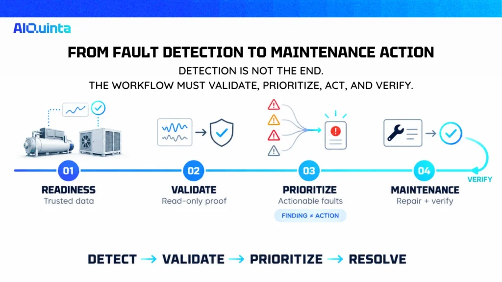
Finding an abnormal condition is only the beginning of the operational workflow.
Step 1: Establish diagnostic readiness
Start with critical chillers and AHUs that have adequate trend histories, identifiable operating modes, and known maintenance ownership.
Review sensor calibration, missing points, trend intervals, equipment mappings, and baseline performance.
Define which faults the existing data can detect and which require additional instrumentation.
Step 2: Validate rules in read-only operation
Deploy diagnostic rules without changing BMS control outputs.
Review findings with facility engineers and compare them with maintenance records and physical inspections.
Track confirmed faults, false positives, missed faults, and time required to identify probable causes.
Tune persistence delays and diagnostic thresholds against observed performance, while preserving protective BMS functions.
Step 3: Rationalize findings before generating alarms
An FDD platform may identify dozens of performance deviations.
Not every deviation should become an urgent alarm or maintenance ticket.
Prioritization should consider fault persistence, asset criticality, available redundancy, service impact, and diagnostic confidence.
The distinction between actionable alarms and informational findings is explored in BMS alarm management.
Step 4: Connect validated faults to maintenance workflows
A useful diagnostic record should contain:
Equipment ID and affected system
Fault condition and detection time
Supporting BMS trends
Operating state and rule version
Probable causes and unresolved uncertainty
Recommended inspection steps
Assigned owner and post-repair verification criteria
This information can support a CMMS work order after review and approval.
Following maintenance, engineers should verify whether the original fault condition has disappeared under comparable operating conditions.
Common Implementation Mistakes and Operational Risks
One frequent mistake is treating every deviation from design values as a fault.
Equipment behaves differently at partial load, during startup, and under changing environmental conditions. Rules that ignore these states produce nuisance findings.
Another mistake is overlooking sensor uncertainty. If two temperature sensors have significant measurement error, a small calculated delta T may be unreliable.
Missing actuator feedback also limits diagnosis. The system can confirm a command but may not confirm mechanical response.
Organizations should also avoid transferring diagnostic rules across buildings without reviewing equipment type, operating sequences, sensor placement, and hydraulic configuration.
Finally, higher automation introduces operational risk.
AI-generated recommendations should not directly override chiller protection functions or modify critical BMS settings without an approved control process.
The Future: Connecting HVAC Diagnostics With Enterprise AI Knowledge
The next opportunity lies in connecting diagnostic evidence with the knowledge required to resolve faults.
A fault engine may identify persistent low delta T. An AI-assisted system could then retrieve relevant equipment manuals, previous maintenance cases, approved troubleshooting procedures, and recent control changes.
This information can help engineers choose the next inspection, document findings, and prepare maintenance actions.
The distinction matters: FDD establishes the technical evidence, while enterprise AI helps retrieve context and coordinate approved workflows.
This direction aligns with broader developments in BMS predictive maintenance, where trends, maintenance history, and asset information support earlier intervention.
AI should remain accountable to validated measurements, engineering rules, and human approval.
Conclusion: Build Diagnosis Around Evidence, Not Alarm Volume
Effective chiller and AHU fault detection requires reliable signals, operating-state awareness, and system-level reasoning.
Chilled-water delta T, power consumption, valve commands, and supply-air temperatures become valuable diagnostic evidence only when interpreted within the equipment’s physical and operational context.
Structured extraction is therefore more than a document automation task. Extracting and organizing BMS telemetry, control sequences, equipment records, and maintenance outcomes can support a larger enterprise AI capability.
The practical priority is to validate the data, implement explainable rules, connect related assets, and verify maintenance outcomes before increasing automation.
FAQs
How can I detect chiller faults from BMS data?
Start with chilled-water temperatures, measured flow, equipment status, power consumption, and condenser conditions. Compare performance with expected values under similar operating loads. Use engineering rules and calibrated models to identify deviations, then verify competing explanations before assigning a root cause.
What does low delta T indicate in a chiller system?
Low chilled-water delta T means the return-to-supply temperature difference is smaller than expected under the evaluated operating conditions. It can result from low load, excess flow, bypassing valves, reduced coil heat transfer, or control problems. It does not independently prove that the chiller is defective.
What is the difference between chiller FDD and predictive maintenance?
Chiller FDD identifies abnormal operation and may diagnose probable causes using current and historical evidence. Predictive maintenance uses condition information and suitable models to estimate developing maintenance needs or future failure risk. Reliable fault detection supports predictive maintenance, but fault classification alone does not establish when equipment will fail.
Turn Enterprise Knowledge Into Autonomous AI Agents
Your Knowledge, Your Agents, Your Control
Your Knowledge, Your Agents, Your Control
Related Articles


Latest Articles